Hardware Engineer, The Video Game
Factorio is an isometric game that boils down to routing products on conveyer belts from their origin to a consuming machine which makes more products to be routed, etc. The analogy to hardware engineers tracing routes on a PCB is a thoroughly explored topic online. The game gives the player access to a digital logic circuit network (known as combinators) that can be used to probe signals from the factory and can be operated on to compute any turing-complete number of goals.
Belt Throughput Counter
A fast belt can move 30 items per second. Eyeballing the throughput at one moment is generally easy, but watching it and accurately measuring counts over several seconds or minutes is harder. I want a way to measure several seconds of throughput and take an average. I can tell at the outset that I will need several components:
- A clock
- An accumulator
- A reset signal
- A shift register
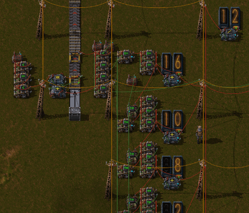
A clock signal C is formed by looping the output of a counter back to itself, plus one. Each game frame processes the digital logic, iterating 60 times per second. To reset the signal once per second I condition the clock output C < 60 so that the output signal looks like 58, 59, 60, 1, 2, ....
In digital logic terms, Factorio combinators are sequential digital logic circuits. This means that they calculate and hold their output on the subsequent frame (or tick) based on the input of the previous tick. This introduces challenges because it means signals lag by one tick for every layer of logic they are processed through.
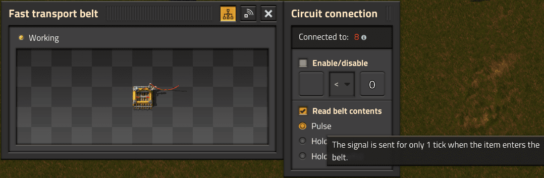
In the same block as the clock signal, a pulse signal A from the target belt is also accumulated, counting once per item which passes. Using the same feedback loop logic as the clock, A counts up once per item. It inherits the same clock reset signal, and therefore resets to zero on the same tick.
The accumulator value A must be saved into the first shift register S0 at the end of each cycle, and it might come as a surprise that this is the most technically challenging portion of this design. Holding a value is easy, just loop the output back to itself, like the clock signal but without the plus one bit. Observe the shift register S0 below with the highlighted green wire looping the output back to the input on one combinator.
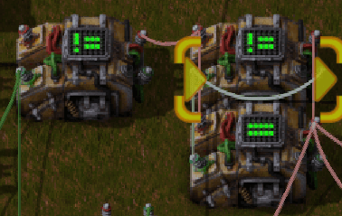
Setting the initial value is no challenge either, just pulse A when C=60. I’ve now saved S0 <= A0, but now ponder the next cycle. The next pulse will come through and save S0 <= S0 + A1. I need a way to reset S0 before A1 pulses.
Pulsing a reset signal R59 when C=59 into S0will zero out the shift register before the accumulator pulses on the next tick. Problem solved. But hang on! The shift registers are meant to be replicated to store multiple cycles in a series, but if the output of each register resets at C=59 then it will not be available to shift the contents into the next register at C=60. Pulsing each shift register a tick earlier is not an option because the end of longer register chains would start to fall meaningfully out of sync with the accumulator timing signals.
The solution I landed on is to use two combinators per shift register to hold each shifted value. The first combinator outputs only when it does not see R59. This allows it to zero its own output to read the accumulator pulse at C=60. The other combinator only outputs when it does see R59, and it outputs the previous value from the first combinator. Taking the sum of both outputs on each tick now results in a steady value that does not glitch during the reset cycle. This can be replicated to produce as long of a chain of shift registers as desired.
If it’s stupid and it works, it’s not stupid.